Hierarchical chip design (with macros)
This guide covers the creation of simple hierarchical chip level macro.
Memory macro is hardened and then the hardened design is used to showcase the integration flow in chip-level macros.
Hardening the mem_1r1w macroblock
In this section, the process of hardening the macroblock mem_1r1w is covered. As these macroblocks will be used in the top-level hierarchy some configurations need to be made.
Keep in mind that these designs are not ready for production and are just used to showcase the capabilities of OpenLane.
Create the memory macro design
Let us create the design. The following command will create a directory design/mem_1r1w/ and one file config.json that will be mostly empty.
./flow.tcl -design ./designs/ci/mem_1r1w -init_design_config -add_to_designs
One of the common mistakes people make is copying existing designs,
like designs/inverter and then they face issues with their configuration.
Always create new designs using -init_design_config.
It will ensure that your configuration is the absolute minimum.
Example of the common issues people face:
They copy inverter design and rename it. Next, run the flow and the router crashes with error 10.
This is caused by enabled “basic placement”,
which works only for designs with a couple of dozen standard cells, not hundreds.
So when you change the basic inverter with a design containing many cells,
the router will not be able to route your design, therefore crashing with cryptic messages.
Create the RTL files
Then we need to create/copy the RTL files. The recommended location for files is design/mem_1r1w/src/. Let us put a simple counter in there.
Create design/mem_1r1w/src/mem_1r1w.v file and put following content:
// SPDX-FileCopyrightText: 2023 Efabless Corporation
//
// Licensed under the Apache License, Version 2.0 (the "License");
// you may not use this file except in compliance with the License.
// You may obtain a copy of the License at
//
//      http://www.apache.org/licenses/LICENSE-2.0
//
// Unless required by applicable law or agreed to in writing, software
// distributed under the License is distributed on an "AS IS" BASIS,
// WITHOUT WARRANTIES OR CONDITIONS OF ANY KIND, either express or implied.
// See the License for the specific language governing permissions and
// limitations under the License.
// SPDX-License-Identifier: Apache-2.0

module mem_1r1w (clk, read_addr, read, read_data, write_addr, write, write_data);
	parameter DEPTH_LOG2 = 4;
	localparam ELEMENTS = 2**DEPTH_LOG2;
	parameter WIDTH = 32;

	input wire clk;

    input wire [DEPTH_LOG2-1:0] read_addr;
    input wire read;
	output reg [WIDTH-1:0] read_data;


	input wire [DEPTH_LOG2-1:0] write_addr;
	input wire write;
	input wire  [WIDTH-1:0] write_data;

reg [WIDTH-1:0] storage [ELEMENTS-1:0];

always @(posedge clk) begin
	if(write) begin
		storage[write_addr] <= write_data;
	end
	if(read)
		read_data <= storage[read_addr];
end

endmodule
Note
Originally we used a very small macroblock as an example, however, there is a known issue: Small macroblocks do not fit the power grid, therefore you need to avoid making small macroblocks.
For this, set the FP_SIZING to absolute and configure DIE_AREA to be bigger than 200um x 200um for sky130.
Configure mem_1r1w
Modify the config.json to include following:
{
    "DESIGN_NAME": "mem_1r1w",
    "VERILOG_FILES": "dir::src/*.v",
    "CLOCK_PORT": "clk",
    "CLOCK_PERIOD": 10.0,
    "DESIGN_IS_CORE": false,
    "FP_PDN_CORE_RING": false,
    "RT_MAX_LAYER": "met4"
}
FP_PDN_MULTILAYER controls the metal levels used for power routing. Set it to false to use only lower levels.
FP_PDN_CORE_RING is set to false to disable a power ring around the macroblock.
RT_MAX_LAYER set to met4 to limit metal layers allowed for routing.
More information on configuration can be found here.
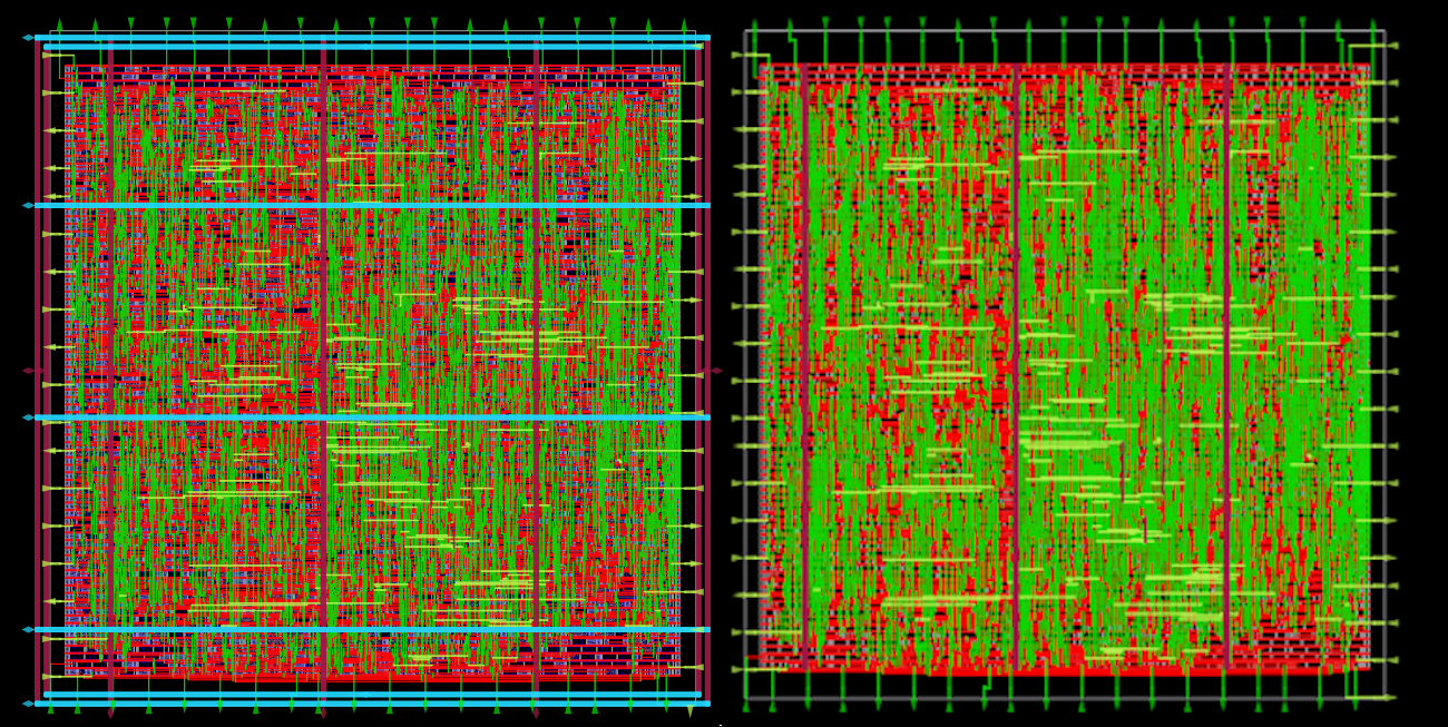
Fig. 1 On the left "FP_PDN_CORE_RING": true, on the right "FP_PDN_CORE_RING": false
Run the flow on the macroblock
Finally, run OpenLane. flow.tcl is the entry point for OpenLane.
The command needs to be run from inside the environment of OpenLane as described in quickstart.
./flow.tcl -design ./designs/ci/mem_1r1w -tag full_guide -overwrite
Analyzing the flow-generated files
You can open the interactive view using the following commands:
./flow.tcl -design ./designs/ci/mem_1r1w -tag full_guide -interactive
package require  openlane
or_gui
Chip level integration
In this section, the integration of previously hardened macroblock is covered. Currently, OpenLane does not support cross-hierarchy timing analysis, so users should avoid multiple hierarchies.
Create chip level
The top-level macroblock is called regfile_2r1w. However, to run the flow we need to prepare the design first.
Create a new design named regfile_2r1w. This design will use the mem_1r1w.
./flow.tcl -design regfile_2r1w -init_design_config -add_to_designs
Integrate the macros
Verilog blackbox is used by the synthesis tool. It tells the synthesis tool the purpose and width of the input and output but does not carry information regarding the timings.
In the OpenRAM macro tutorial, the alternative with the Liberty file is described.
Liberty flow contains the timings, unfortunately, OpenLane does not generate the Liberty output. This means that the only remaining option is the Verilog Blackbox flow.
Warning
The users should be careful when making subcomponents or blackboxes that have parameters, because this may cause behavior mismatches between RTL and the final GDS.
Create the verilog blackbox:
(*blackbox*)

module mem_1r1w (clk, read_addr, read, read_data, write_addr, write, write_data);
	parameter DEPTH_LOG2 = 4;
	localparam ELEMENTS = 2**DEPTH_LOG2;
	parameter WIDTH = 32;

	input wire clk;

    input wire [DEPTH_LOG2-1:0] read_addr;
    input wire read;
	output reg [WIDTH-1:0] read_data;


	input wire [DEPTH_LOG2-1:0] write_addr;
	input wire write;
	input wire  [WIDTH-1:0] write_data;

endmodule
Then add VERILOG_FILES_BLACKBOX, EXTRA_LEFS and EXTRA_GDS_FILES to the config.json in the regfile_2r1w:
{
  "DESIGN_NAME": "regfile_2r1w",
  "VERILOG_FILES": "dir::src/*.v",
  "CLOCK_PORT": "clk",
  "CLOCK_PERIOD": 10.0,
  "FP_PDN_MULTILAYER": true,

  "EXTRA_LEFS": "/openlane/designs/ci/mem_1r1w/runs/full_guide/results/final/lef/mem_1r1w.lef",
  "EXTRA_GDS_FILES": "/openlane/designs/ci/mem_1r1w/runs/full_guide/results/final/gds/mem_1r1w.gds",
  "VERILOG_FILES_BLACKBOX": "dir::bb/*.v"
}
This will add the LEF abstract representation of the macroblock. This abstraction file contains only layers required by tools. In contrast, GDS contains all of the layers and is used to generate the final GDS file. Mismatches between these files is not allowed. It is the responsibility of the users to ensure that they match.
Warning
Check for name collisions between the blackboxed macroblocks that have the same name but different parameters, to avoid a behavioral mismatch. This is a known issue documented here.
The PDN straps will be routed in opposite directions.
In locations where the two routings cross each other,
VIAs connecting the layers are added. When FP_PDN_MULTILAYER is set to true then higher layers (met5 in sky130) are used.
If it is set to false then VIAs will be missing and you will get LVS issues.
Verilog files
Create the RTL files for the macroblock regfile_2r1w.
The file is located in newly created design path designs/ci/regfile_2r1w/src/regfile_2r1w.v and has following content:
// SPDX-FileCopyrightText: 2023 Efabless Corporation
//
// Licensed under the Apache License, Version 2.0 (the "License");
// you may not use this file except in compliance with the License.
// You may obtain a copy of the License at
//
//      http://www.apache.org/licenses/LICENSE-2.0
//
// Unless required by applicable law or agreed to in writing, software
// distributed under the License is distributed on an "AS IS" BASIS,
// WITHOUT WARRANTIES OR CONDITIONS OF ANY KIND, either express or implied.
// See the License for the specific language governing permissions and
// limitations under the License.
// SPDX-License-Identifier: Apache-2.0
module regfile_2r1w(
    input  wire                     clk,
    input  wire                     rst_n,

    input  wire                     rs1_read,
    input  wire [DEPTH_LOG2-1:0]    rs1_addr,
    output wire [WIDTH-1:0]         rs1_rdata,

    input  wire                     rs2_read,
    input  wire [DEPTH_LOG2-1:0]    rs2_addr,
    output wire [WIDTH-1:0]         rs2_rdata,

    input  wire [DEPTH_LOG2-1:0]    rd_addr,
    input  wire [WIDTH-1:0]         rd_wdata,
    input  wire                     rd_write
);

parameter WIDTH = 32;
parameter DEPTH_LOG2 = 4;

wire                         write = !rst_n  ? 1 : (rd_write && (rd_addr != 0));
wire [DEPTH_LOG2-1:0] write_addr = !rst_n  ? 0 : rd_addr;
wire [WIDTH-1:0]         write_data = !rst_n  ? 0 : rd_wdata;


mem_1r1w #(.DEPTH_LOG2(DEPTH_LOG2), .WIDTH(WIDTH)) lane0(
    .clk(clk),

    .read_addr(rs1_addr),
    .read(rs1_read),
    .read_data(rs1_rdata),

    .write(write),
    .write_addr(write_addr),
    .write_data(write_data)
);


mem_1r1w #(.DEPTH_LOG2(DEPTH_LOG2), .WIDTH(WIDTH)) lane1(
    .clk(clk),

    .read_addr(rs2_addr),
    .read(rs2_read),
    .read_data(rs2_rdata),

    .write(write),
    .write_addr(write_addr),
    .write_data(write_data)
);


endmodule
Run the flow
Run the flow. It is expected for the flow to fail. In the next step, explanation is provided.
./flow.tcl -design regfile_2r1w -tag full_guide_broken_aspect_ratio -overwrite
First issue
Flow is expected to fail.
[ERROR]: during executing openroad script /openlane/scripts/openroad/replace.tcl
[ERROR]: Exit code: 1
[ERROR]: full log: designs/ci/regfile_2r1w/runs/full_guide/logs/placement/9-global.log
[ERROR]: Last 10 lines:
[INFO GPL-0015] CoreAreaUxUy: 489440 495040
[INFO GPL-0016] CoreArea: 234294707200
[INFO GPL-0017] NonPlaceInstsArea: 124707104000
[INFO GPL-0018] PlaceInstsArea: 117229672450
[INFO GPL-0019] Util(%): 106.97
[INFO GPL-0020] StdInstsArea: 454185600
[INFO GPL-0021] MacroInstsArea: 116775486850
[ERROR GPL-0301] Utilization exceeds 100%.
Error: replace.tcl, 91 GPL-0301
child process exited abnormally
To debug this issue, open the OpenROAD GUI:
./flow.tcl -design regfile_2r1w -interactive -tag full_guide_broken_aspect_ratio
package require  openlane
or_gui
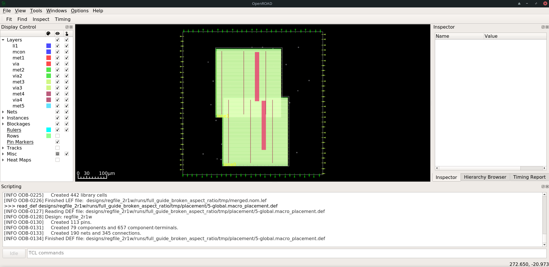
As can be observed in the image, the placement of the mem_1r1w instances failed.
It was unable to place the macroblocks inside the DIE_AREA.
While the area is enough, there is no combination of placement for these cells that fits.
All of the possible placements of these cells overlap.
Change the FP_ASPECT_RATIO value to 2.
This will make the floorplan a rectangle instead of a square and the rectangle will be double in height compared to width.
More information regarding floorplanning is available Hardening Macros guide.
config.json should look like this:
{
    "DESIGN_NAME": "regfile_2r1w",
    "VERILOG_FILES": "dir::src/*.v",
    "CLOCK_PORT": "clk",
    "CLOCK_PERIOD": 10.0,
    "DESIGN_IS_CORE": true,

    "FP_ASPECT_RATIO": 2,
    "EXTRA_LEFS":      "/openlane/designs/mem_1r1w/runs/full_guide/results/final/lef/mem_1r1w.lef",
    "EXTRA_GDS_FILES": "/openlane/designs/mem_1r1w/runs/full_guide/results/final/gds/mem_1r1w.gds",
    "VERILOG_FILES_BLACKBOX": "dir::bb/*.v"
}
There is no need to change the default PDN configuration.
It is going to create power straps on met5 and connect the macro
that has power straps on met4 using vias.
Run the flow again
Run the flow again. This time it should no longer fail.
./flow.tcl -design regfile_2r1w -tag full_guide -overwrite
Analyzing the results
Note
set_def currently overwrites the DEF file instead of temporarily changing it.
This guide will be updated with another command that does not overwrite the DEF.
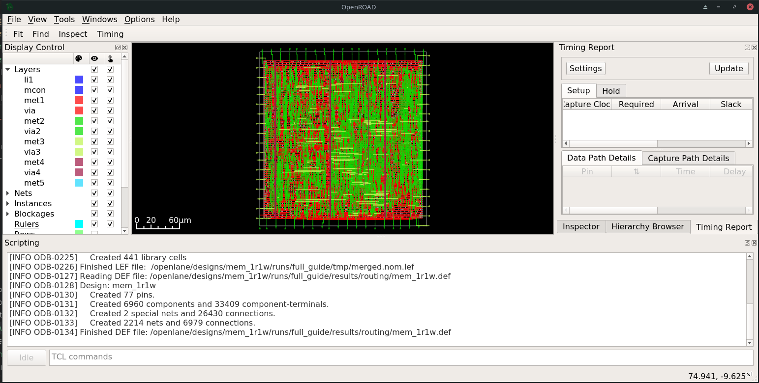
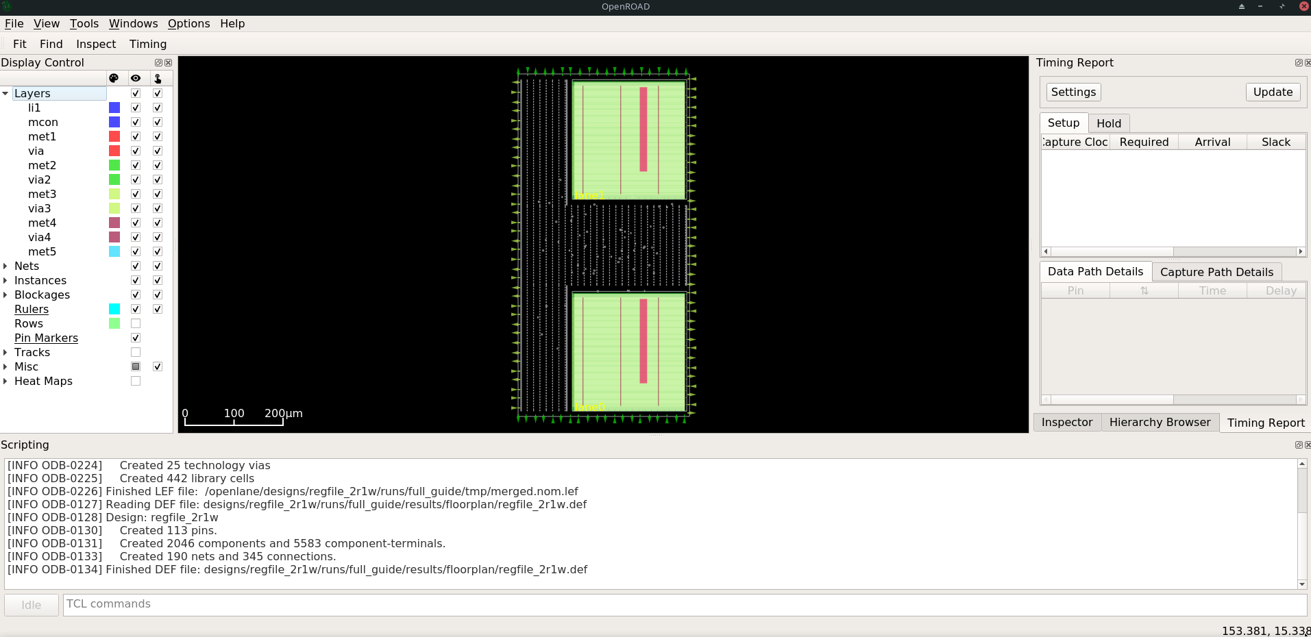
Open OpenROAD GUI to view the results of the flow.
./flow.tcl -design regfile_2r1w -interactive -tag full_guide

# in interactive session:
package require openlane
set_def designs/ci/regfile_2r1w/runs/full_guide/results/final/def/regfile_2r1w.def
or_gui
# Empty newline to force above line to execute
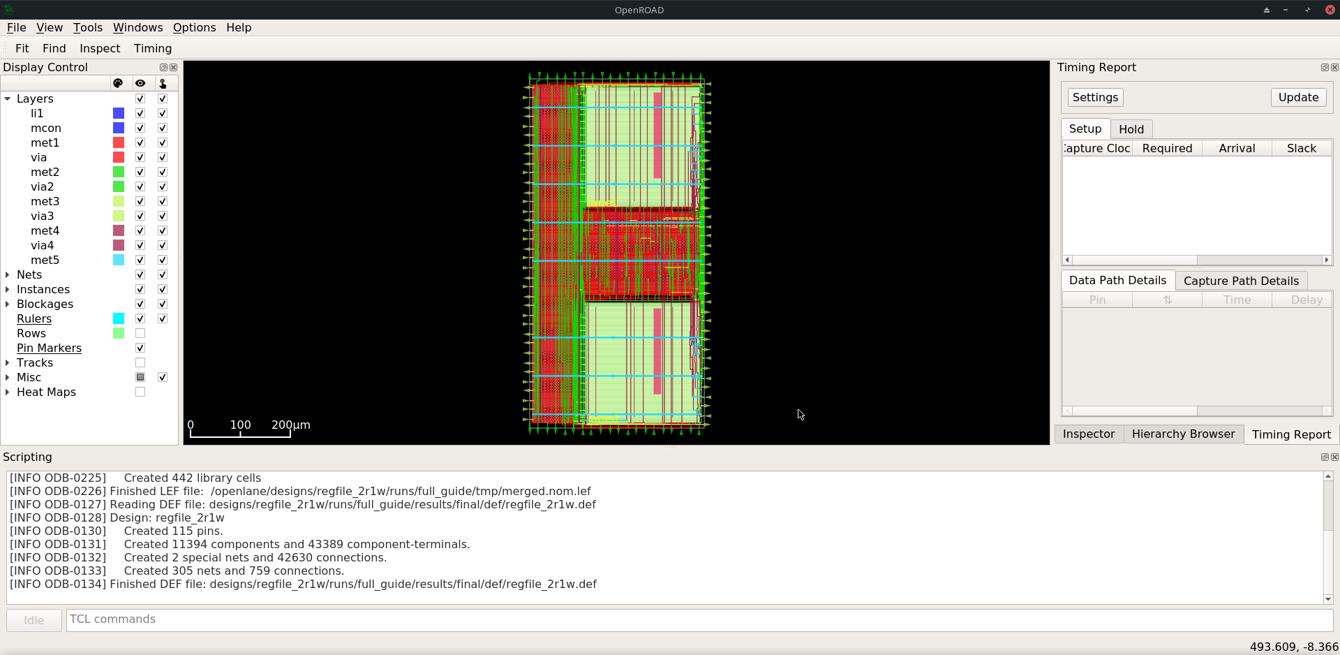
Fig. 2 OpenROAD GUI with loaded final DEF file
If you want to load different DEF file use set_def command. For example:
./flow.tcl -design regfile_2r1w -interactive -tag full_guide
package require openlane
set_def designs/ci/regfile_2r1w/runs/full_guide/results/floorplan/regfile_2r1w.def
or_gui
Each run has following structure:
├── logs OR reports OR results OR tmp
│   ├── cts
│   ├── floorplan
│   ├── placement
│   ├── routing
│   ├── signoff
│   └── synthesis
├── runtime.yaml
└── warnings.log
There are 4 directories logs reports results and tmp.
In each of these directories, there are multiple directories. Directories are named according to the stage they belong to.
Directory results contain the results (outputs) of each step. For example content of the results/cts:
designs/ci/regfile_2r1w/runs/full_guide/results/cts
├── regfile_2r1w.def
├── regfile_2r1w.resized.v
├── regfile_2r1w.sdc
└── regfile_2r1w.v
DEF files can be loaded using the steps provided above.
Finally output of OpenLane can be found in designs/ci/regfile_2r1w/runs/full_guide/results/final:
designs/ci/regfile_2r1w/runs/full_guide/results/final
├── def
│   └── regfile_2r1w.def
├── gds
│   └── regfile_2r1w.gds
├── lef
│   └── regfile_2r1w.lef
├── mag
│   └── regfile_2r1w.mag
├── maglef
│   └── regfile_2r1w.mag
├── sdc
│   └── regfile_2r1w.sdc
├── sdf
│   └── regfile_2r1w.sdf
├── spef
│   └── regfile_2r1w.spef
├── spi
│   └── lvs
│       └── regfile_2r1w.spice
└── verilog
    └── gl
        └── regfile_2r1w.v
Directory logs contain log files of each step. Steps are enumerated. For example content of the logs/:
designs/ci/regfile_2r1w/runs/full_guide/logs
├── cts
│   ├── 14-cts.log
│   ├── 15-write_verilog.log
│   ├── 16-resizer.log
│   └── 17-write_verilog.log
├── floorplan
│   ├── 3-initial_fp.log
│   ├── 4-io.log
│   ├── 7-tap.log
│   └── 8-pdn.log
├── placement
│   ├── 10-resizer.log
│   ├── 11-write_verilog.log
│   ├── 12-remove_buffers_from_ports.log
│   ├── 13-detailed.log
│   ├── 5-global.log
│   ├── 6-basic_mp.log
│   └── 9-global.log
├── routing
│   ├── 18-resizer.log
│   ├── 19-write_verilog.log
│   ├── 20-diode_legalization.log
│   ├── 21-global.log
│   ├── 22-fill.log
│   ├── 23-write_verilog_global.log
│   ├── 24-detailed.log
│   └── 25-write_verilog_detailed.log
├── signoff
│   ├── 26-parasitics_extraction.min.log
│   ├── 27-parasitics_multi_corner_sta.min.log
│   ├── 28-parasitics_extraction.max.log
│   ├── 29-parasitics_multi_corner_sta.max.log
│   ├── 30-parasitics_extraction.nom.log
│   ├── 31-parasitics_sta.log
│   ├── 32-parasitics_multi_corner_sta.log
│   ├── 33-irdrop.log
│   ├── 34-gdsii.log
│   ├── 34-gds_ptrs.log
│   ├── 34-lef.log
│   ├── 34-maglef.log
│   ├── 35-gdsii-klayout.log
│   ├── 36-xor.log
│   ├── 37-spice.log
│   ├── 38-write_powered_def.log
│   ├── 40-lef.log
│   ├── 40-regfile_2r1w.lef.json
│   ├── 40-regfile_2r1w.lef.log
│   ├── 40-regfile_2r1w.lvs.lef.log
│   ├── 41-drc.log
│   └── 42-antenna.log
└── synthesis
    ├── 1-synthesis.log
    └── 2-sta.log
Directory reports contains all of the reports from the corresponding stage.
It is recommended to check the reports for power, timings, etc. This allows getting a better understanding of the underlying flow.
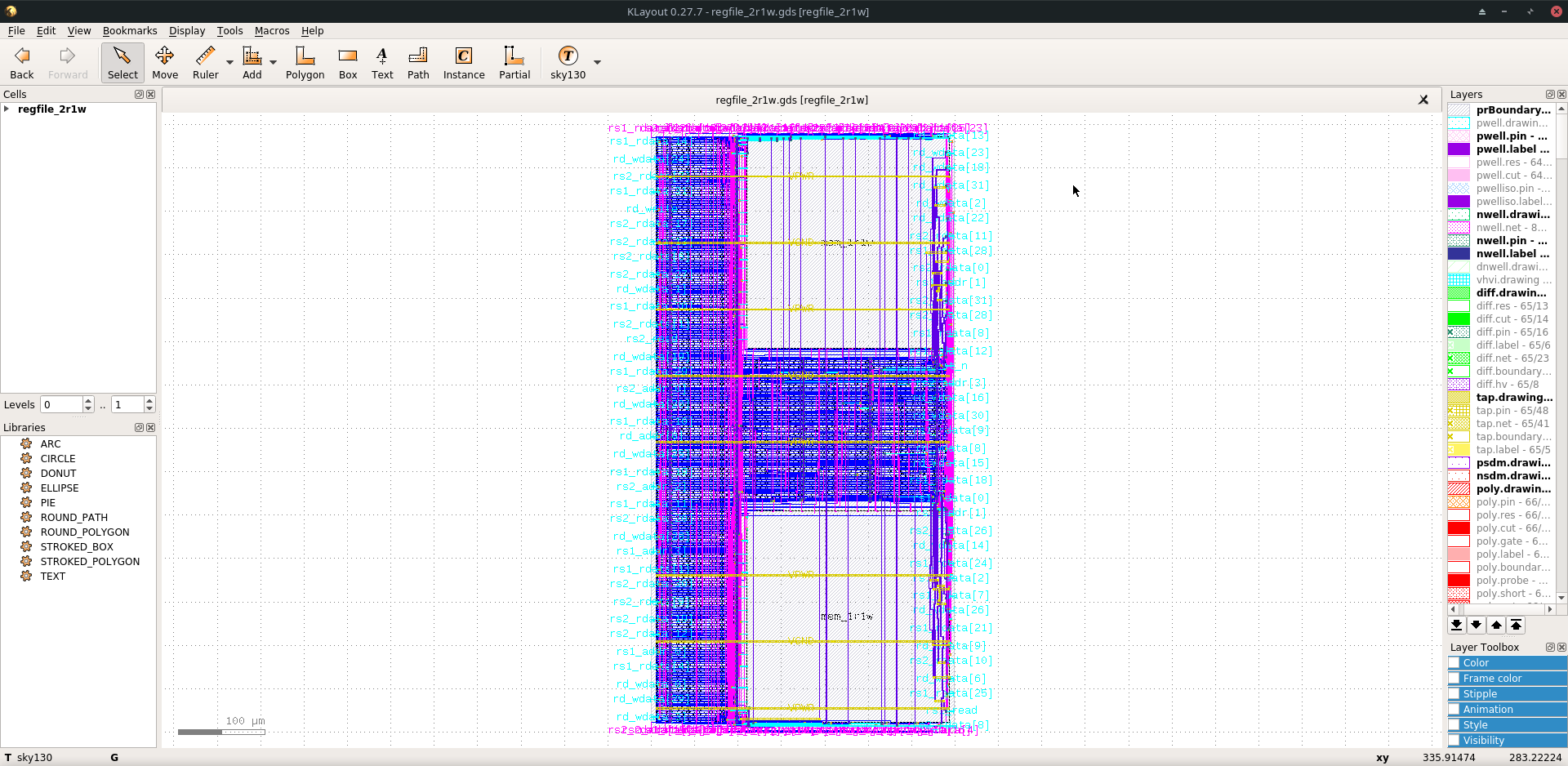
Finally, open the final layout.
klayout -e -nn $PDK_ROOT/sky130A/libs.tech/klayout/tech/sky130A.lyt \
   -l $PDK_ROOT/sky130A/libs.tech/klayout/tech/sky130A.lyp \
   ./designs/ci/regfile_2r1w/runs/full_guide/results/final/gds/regfile_2r1w.gds
Exploring your designs
Take a look at some reports.
Here’s an excerpt from designs/ci/mem_1r1w_00/runs/full_guide/reports/signoff/##-rcx_sta.summary.rpt:
===========================================================================
report_worst_slack -max (Setup)
============================================================================
worst slack 4.66

===========================================================================
report_worst_slack -min (Hold)
============================================================================
worst slack 0.03
Detailed setup (max) timing path reports. Content of designs/ci/mem_1r1w/runs/full_guide/reports/signoff/##-rcx_sta.max.rpt:
===========================================================================
report_checks -path_delay max (Setup)
============================================================================

======================= Slowest Corner ===================================

Startpoint: write_addr[1] (input port clocked by clk)
Endpoint: _3436_ (rising edge-triggered flip-flop clocked by clk)
Path Group: clk
Path Type: max
Corner: Slowest

Fanout     Cap    Slew   Delay    Time   Description
-----------------------------------------------------------------------------
                        0.00    0.00   clock clk (rise edge)
                        0.00    0.00   clock network delay (propagated)
                        2.00    2.00 v input external delay
                0.02    0.01    2.01 v write_addr[1] (in)
1    0.00                           write_addr[1] (net)
                0.02    0.00    2.01 v input8/A (sky130_fd_sc_hd__dlymetal6s2s_1)
                0.18    0.37    2.38 v input8/X (sky130_fd_sc_hd__dlymetal6s2s_1)
4    0.02                           net8 (net)
                0.18    0.00    2.38 v _2019_/A (sky130_fd_sc_hd__or3b_2)
                0.23    1.29    3.67 v _2019_/X (sky130_fd_sc_hd__or3b_2)
2    0.01                           _0833_ (net)
                0.23    0.00    3.67 v _2020_/A (sky130_fd_sc_hd__inv_2)
                0.09    0.17    3.84 ^ _2020_/Y (sky130_fd_sc_hd__inv_2)
3    0.01                           _0834_ (net)
                0.09    0.00    3.84 ^ _2432_/C (sky130_fd_sc_hd__and3_2)
                0.24    0.56    4.39 ^ _2432_/X (sky130_fd_sc_hd__and3_2)
5    0.03                           _1054_ (net)
                0.24    0.00    4.39 ^ _2433_/A (sky130_fd_sc_hd__buf_4)
                0.26    0.44    4.84 ^ _2433_/X (sky130_fd_sc_hd__buf_4)
10    0.06                           _1055_ (net)
                0.26    0.01    4.85 ^ _2450_/S (sky130_fd_sc_hd__mux2_1)
                0.11    0.81    5.66 v _2450_/X (sky130_fd_sc_hd__mux2_1)
1    0.00                           _1064_ (net)
                0.11    0.00    5.66 v _2451_/A (sky130_fd_sc_hd__clkbuf_1)
                0.05    0.18    5.84 v _2451_/X (sky130_fd_sc_hd__clkbuf_1)
1    0.00                           _0424_ (net)
                0.05    0.00    5.84 v _3436_/D (sky130_fd_sc_hd__dfxtp_1)
                                5.84   data arrival time

                        10.00   10.00   clock clk (rise edge)
                        0.00   10.00   clock source latency
                0.18    0.12   10.12 ^ clk (in)
1    0.02                           clk (net)
                0.18    0.00   10.12 ^ clkbuf_0_clk/A (sky130_fd_sc_hd__clkbuf_16)
                0.12    0.31   10.43 ^ clkbuf_0_clk/X (sky130_fd_sc_hd__clkbuf_16)
4    0.06                           clknet_0_clk (net)
                0.12    0.00   10.43 ^ clkbuf_2_3__f_clk/A (sky130_fd_sc_hd__clkbuf_16)
                0.18    0.33   10.76 ^ clkbuf_2_3__f_clk/X (sky130_fd_sc_hd__clkbuf_16)
10    0.11                           clknet_2_3__leaf_clk (net)
                0.18    0.00   10.76 ^ clkbuf_leaf_17_clk/A (sky130_fd_sc_hd__clkbuf_16)
                0.08    0.27   11.03 ^ clkbuf_leaf_17_clk/X (sky130_fd_sc_hd__clkbuf_16)
11    0.03                           clknet_leaf_17_clk (net)
                0.08    0.00   11.03 ^ _3436_/CLK (sky130_fd_sc_hd__dfxtp_1)
                        -0.25   10.78   clock uncertainty
                        0.00   10.78   clock reconvergence pessimism
                        -0.26   10.52   library setup time
                                10.52   data required time
-----------------------------------------------------------------------------
                                10.52   data required time
                                -5.84   data arrival time
-----------------------------------------------------------------------------
                                4.68   slack (MET)
Demo: Debugging LVS issues due to PDN issues
Copy the original regfile_2r1w as regfile_2r1w_design_not_core. Change FP_PDN_MULTILAYER to false.
{
    "DESIGN_NAME": "regfile_2r1w",
    "VERILOG_FILES": "dir::src/*.v",
    "CLOCK_PORT": "clk",
    "CLOCK_PERIOD": 10.0,
    "FP_PDN_MULTILAYER": false,

    "FP_ASPECT_RATIO": 2,
    "EXTRA_LEFS":      "/openlane/designs/ci/mem_1r1w/runs/full_guide/results/final/lef/mem_1r1w.lef",
    "EXTRA_GDS_FILES": "/openlane/designs/ci/mem_1r1w/runs/full_guide/results/final/gds/mem_1r1w.gds",
    "VERILOG_FILES_BLACKBOX": "dir::bb/*.v"
}
Then run the flow:
./flow.tcl -design regfile_2r1w_design_not_core -tag full_guide -overwrite
The following error is expected:
[STEP 39]
[INFO]: Running Magic Spice Export from LEF (log: designs/ci/regfile_2r1w_design_not_core/runs/full_guide/logs/signoff/39-spice.log)...
[STEP 40]
[INFO]: Writing Powered Verilog (log: ../dev/null)...
[STEP 41]
[INFO]: Writing Verilog...
[STEP 42]
[INFO]: Running LEF LVS...
[ERROR]: There are LVS errors in the design: See 'designs/ci/regfile_2r1w_design_not_core/runs/full_guide/logs/signoff/42-regfile_2r1w.lvs.lef.log' for details.
[INFO]: Saving current set of views in 'designs/ci/regfile_2r1w_design_not_core/runs/full_guide/results/final'...
[INFO]: Generating final set of reports...
[INFO]: Created manufacturability report at 'designs/ci/regfile_2r1w_design_not_core/runs/full_guide/reports/manufacturability.rpt'.
[INFO]: Created metrics report at 'designs/ci/regfile_2r1w_design_not_core/runs/full_guide/reports/metrics.csv'.
[INFO]: Saving runtime environment...
[ERROR]: Flow failed.

    while executing
"flow_fail"
    (procedure "quit_on_lvs_error" line 12)
    invoked from within
"quit_on_lvs_error -log $count_lvs_log"
    (procedure "run_lvs" line 79)
    invoked from within
"run_lvs"
    (procedure "run_lvs_step" line 10)
    invoked from within
"[lindex $step_exe 0] [lindex $step_exe 1] "
    (procedure "run_non_interactive_mode" line 52)
    invoked from within
"run_non_interactive_mode {*}$argv"
    invoked from within
"if { [info exists flags_map(-interactive)] || [info exists flags_map(-it)] } {
    if { [info exists arg_values(-file)] } {
        run_file [file nor..."
    (file "./flow.tcl" line 401)
Check the log designs/ci/regfile_2r1w_design_not_core/runs/full_guide/logs/signoff/42-regfile_2r1w.lvs.lef.log.
LVS reports:
    net count difference = 4
    device count difference = 0
    unmatched nets = 11
    unmatched devices = 22
    unmatched pins = 0
    property failures = 0

Total errors = 37
The router will fail if it is unable to route the signals.
Therefore the issue is in the PDN stage.
Use or_gui to help debug this issue.
./flow.tcl -design regfile_2r1w_design_not_core -interactive -tag full_guide
package require openlane
set_def designs/ci/regfile_2r1w_design_not_core/runs/full_guide/results/final/def/regfile_2r1w.def
or_gui
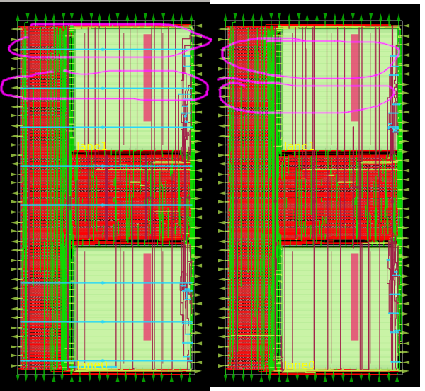
Fig. 3 Left picture is for working case. Right picture is the case with PDN issues
The submacros are by default logically connected to VPWR/VGND power domain.
As can be seen, the PDN is missing the power straps in layer met5.
Therefore the layout, does not have connections to the submacro, while the net is logically connected.
This is expected as it was disabled by setting FP_PDN_MULTILAYER to false above.
Of course, reverting the change fixes this issue.
Note
In the future, OpenDB will be used instead of DEF/LEF flow.